Digital Automatic Manifold Systems
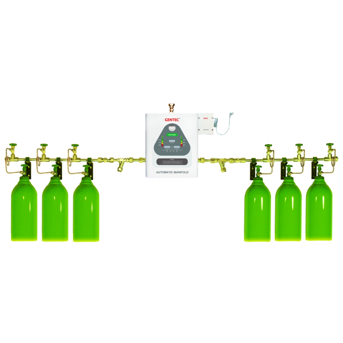
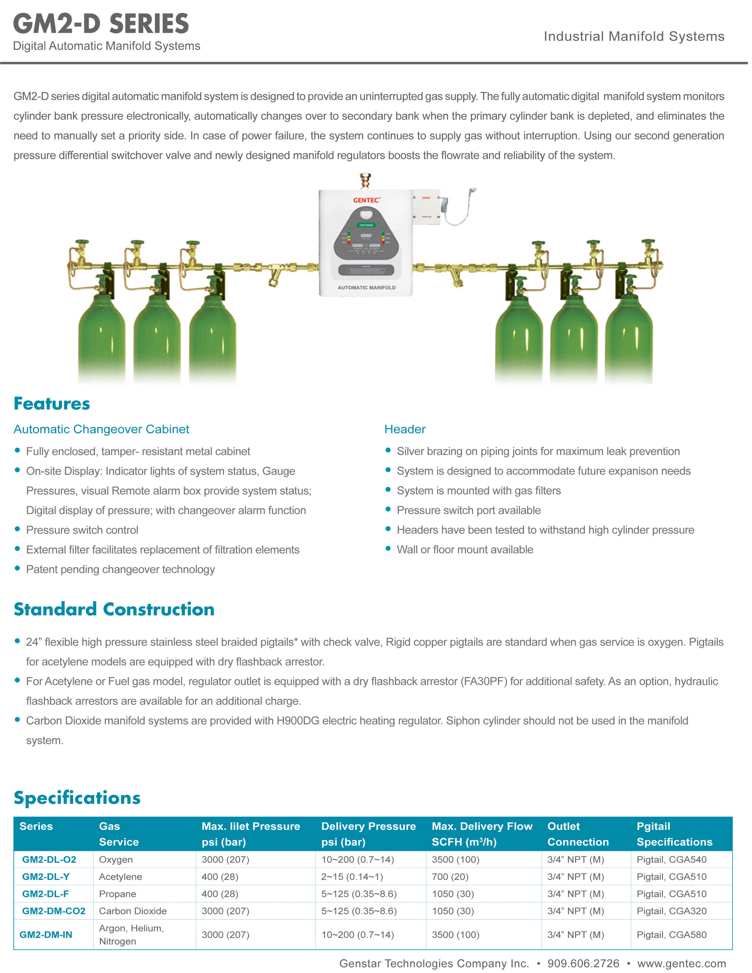
GM2-D series digital automatic manifold system is designed to provide an uninterrupted gas supply. The fully automatic digital manifold system monitors cylinder bank pressure electronically, automatically changes over to secondary bank when the primary cylinder bank is depleted, and eliminates the need to manually set a priority side. In case of power failure, the system continues to supply gas without interruption. Using our second generation pressure differential switchover valve and newly designed manifold regulators boosts the flowrate and reliability of the system.
Features
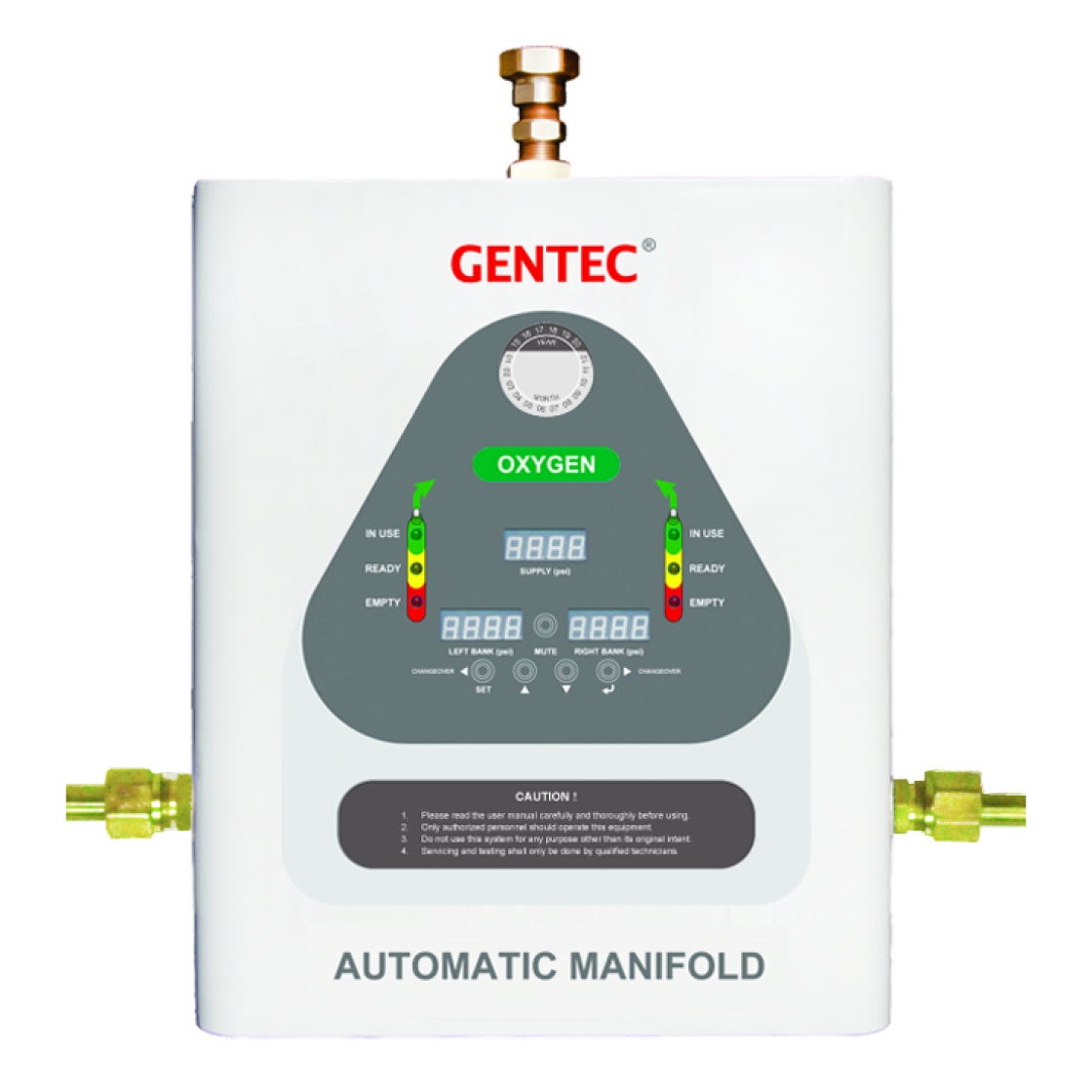
Automatic Changeover Cabinet
• Fully enclosed, tamper-resistant metal cabinet
• On-site Display: Indicator lights of system status, Gauge Pressures, visual Remote alarm box provide system status; Digital display of pressure; with changeover alarm function
• Pressure switch control
• External filter facilitates replacement of filtration elements
• Patent pending changeover technology
Header
• Silver brazing on piping joints for maximum leak prevention
• System is designed to accommodate future expanison needs
• System is mounted with gas filters
• Pressure switch port available
• Headers have been tested to withstand high cylinder pressure
• Wall or floor mount available
Standard Construction
24" flexible pressure stainless steel braided pigtails* with check valve, Rigid copper pigtails are standard when gas service is oxygen. Carbon Dioxide manifold systems are provided with H900DG electric heating regulator. Siphon cylinder should not be used in the manifold system.
Inquire about this product
Contact Us
Hours
Phone
Fax
Address
Chino, CA 91710, USA
Ordering Information
| GM2-D | L | - O2 | - U | - ( 5L - 5R | - S | 2 ) |
| Series | Delivery Pressure | Gas Service | Standard Code | Number of Cylinders (left-hand / right-hand) | Manifold System Layout | Cylinder Valve Spacing |
| Automatic Manifold System (Digital) | USA (ISO) L: 55 psi (0.5 MPa) M: 100 psi (0.8 MPa) H: 185 psi (1 MPa) | O2: Oxygen AIR: Air N2O: Nitrous Oxide CO2: Carbon Dioxide IN: Argon, Helium, Nitrogen | U: USA Standard E: ISO Standard UE: Canada Standard | 1L-2R: One cylinder on the left, Two cylinders on the right 5L-5R: Five cylinders on the left, Five cylinders on the Right
Note: Direction of piping (Right or Left) is indicated by facing the manifold. | S: Standard layout L: "L" Shape layout U: "U" shape layout D: Crossover layout X: Staggered layout | 1: 5" (127 mm) 2: 10" (254 mm) 3: 13" (330 mm) 4: 18" (457 mm) |
Specifications
| Series | Gas Service | Max. Inlet Pressure psi (bar) | Delivery Pressure psi (bar) | Max. Delivery Flow SCFH (m3/h) | Outlet Connection | Pigtail Specifications |
| GM2-DL-O2 | Oxygen | 300 (207) | 5~125 (0.35~8.6) | 3500 (100) | 3/4" NPT (M) | Pigtail, CGA540 |
| GM2-DM-AIR | Medical Air | 300 (207) | 10~200 (0.7~14) | 3500 (100) | 3/4" NPT (M) | Pigtail, CGA346 |
| GM2-DL-N2O | Nitrous Oxide | 300 (207) | 55, 100, 185 (5, 8, 10) | 1750 (50) | 3/4" NPT (M) | Pigtail, CGA326 |
| GM2-DM-CO2 | Carbon Dioxide | 2175 (150) | 10~200 (0.7~14) | 1050 (30) | 3/4" NPT (M) | Pigtail, CGA320 |
| GM2-DM-IN | Argon, Helium, Nitrogen | 300 (207) | 10~200 (0.7~14) | 3500 (100) | 3/4" NPT (M) | Pigtail, CGA580 |
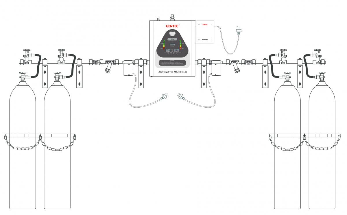
Manifold System Layouts
Restrictions