


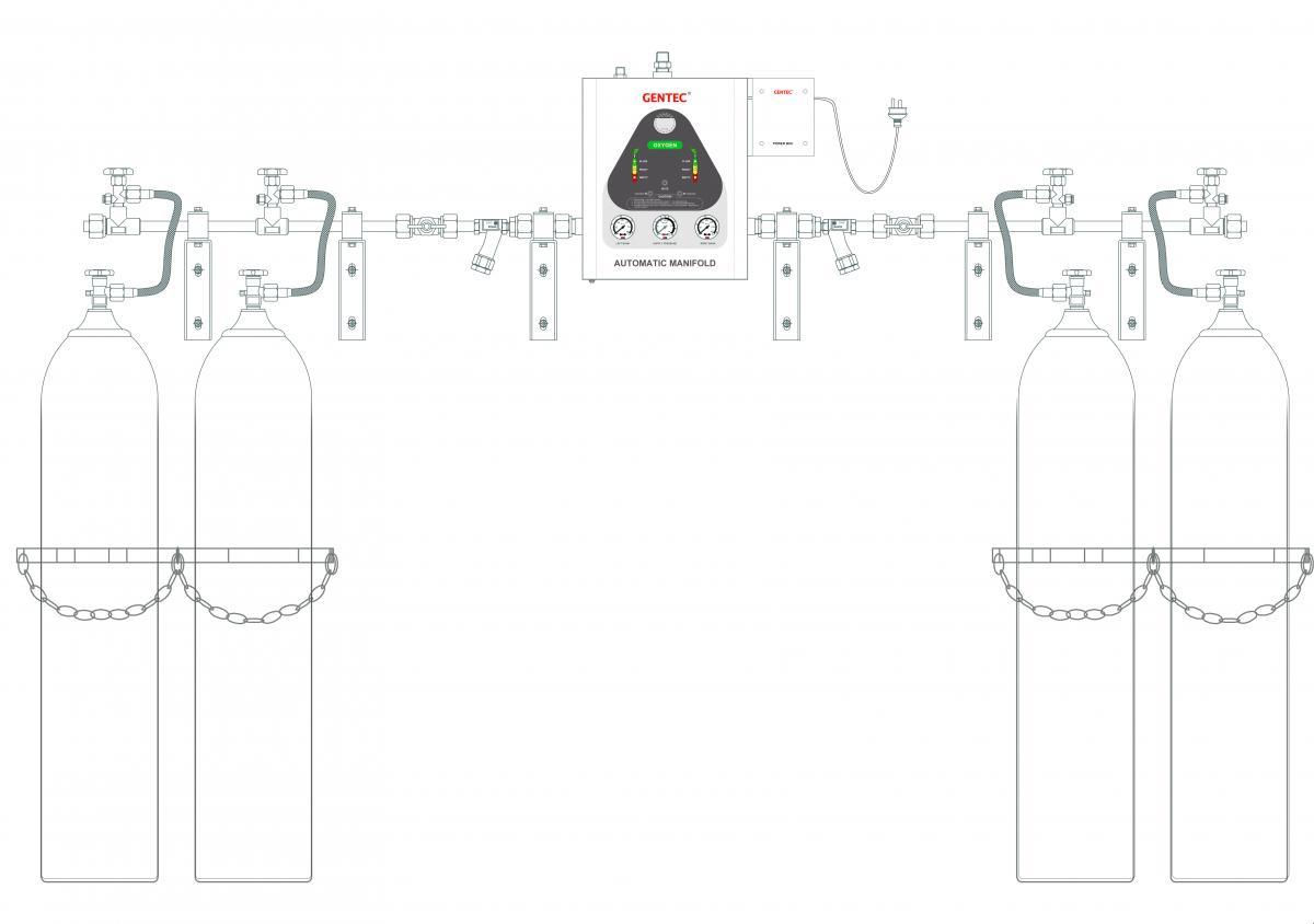
GM2-A series automatic manifold system is designed to provide an uninterrupted gas supply without any manual adjustments. This system automatically changes over when the primary cylinder bank is depleted. Even in case of power failure, the system continues to supply gas without interruption.
Features
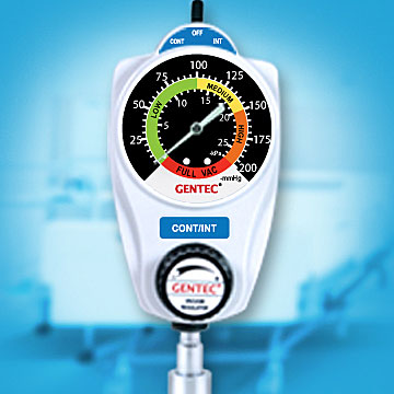
Automatic Changeover Cabinet
• Fully enclosed, tamper-resistant metal cabinet
• Light indicators provide system status
• Systems for fuel gas come with an anti-explosive device
• External filter facilitates replacement of filtration elements
Header
• Silver brazing on piping joints for maximum leak prevention
• System is designed to accommodate future expansion needs
• System is mounted with gas filters
• Pressure switch port available
• Headers have been tested to withstand high cylinder pressure
• Wall or floor mount available
Standard Constuction
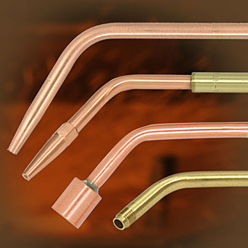
• 24" flexible high pressure stainless steel braided pigtails with check valve. Rigid copper pigtails are standard when gas service is oxygen. Pigtails for acetylene models are equipped with dry flaskback arrestor.
• Carbon Dioxide manifold systems are provided with H900G electric heating regulator. Siphon cylinder should not be used in the manifold system.
| GM2-A | L | - O2 | - U | - ( 5L - 5R | - S | 2 ) |
| Series | Delivery Pressure | Gas Service | Standard Code | Number of Cylinders (left-hand / right-hand) | Manifold System Layout | Cylinder Valve Spacing |
| Automatic Manifold System (Pressure Gauge) | USA (ISO) L: 55 psi (0.5 MPa) M: 100 psi (0.8 MPa) H: 185 psi (1 MPa) | O2: Oxygen AIR: Air N2O: Nitrous Oxide CO2: Carbon Dioxide IN: Argon, Helium, Nitrogen | U: USA Standard E: ISO Standard UE: Standard | 1L-2R: One cylinder on the left, Two cylinders on the right 5L-5R: Five cylinders on the left, Five cylinders on the Right
Note: Direction of piping (Right or Left) is indicated by facing the manifold. | S: Standard layout L: "L" Shape layout U: "U" shape layout D: Crossover layout X: Staggered layout | 1: 5" (127 mm) 2: 10" (254 mm) 3: 13" (330 mm) 4: 18" (457 mm) |
| Series | Gas Service | Max. Inlet Pressure psi (bar) | Delivery Pressure psi (bar) | Max. Delivery Flow SCFH (m3/h) | Outlet Connection | Pigtail Specifications |
| GM2-AL-O2 |
Oxygen |
3000 (207) |
10~200 (0.7~14) |
3500 (100) |
3/4” NPT (M) |
Pigtail, CGA540 |
| GM2-AM-AIR |
Medical Air |
3000 (207) |
5~125 (0.35~8.6) |
3500 (100) |
3/4” NPT (M) |
Pigtail, CGA346 |
| GM2-AL-N2O |
Nitrous Oxide |
3000 (207) |
55, 100, 185 (5,8,10) |
1750 (50) |
3/4” NPT (M) |
Pigtail, CGA326 |
| GM2-AM-CO2 |
Carbon Dioxide |
2175 (150) |
5~125 (0.35~8.6) |
1050 (30) |
3/4” NPT (M) |
Pigtail, CGA320 |
| GM2-AM-IN |
Argon, Helium, Nitrogen |
3000 (207) |
10~200 (0.7~14) |
3500 (100) |
3/4” NPT (M) |
Pigtail, CGA580 |
Gas Service | W in.(mm) | H1 in.(mm) | H2 in.(mm) |
| Oxygen, Air, Argon, Nitrogen, Helium | 41.3 (1050) | 15.8 (400) | 55.1 (1400) |
| Carbon Dioxide | 55.5 (1410) | 15.8 (400) | 55.1 (1400) |
Standard Layout | "L" Shape Layout | "U" Shape Layout | Crossover Layout | Staggered Layout |
|  |  |  |  |
Spec Sheet Files
| Attachment | Size |
|---|---|
| 2.36 MB |